Analogue to Digital Converter (ADC)
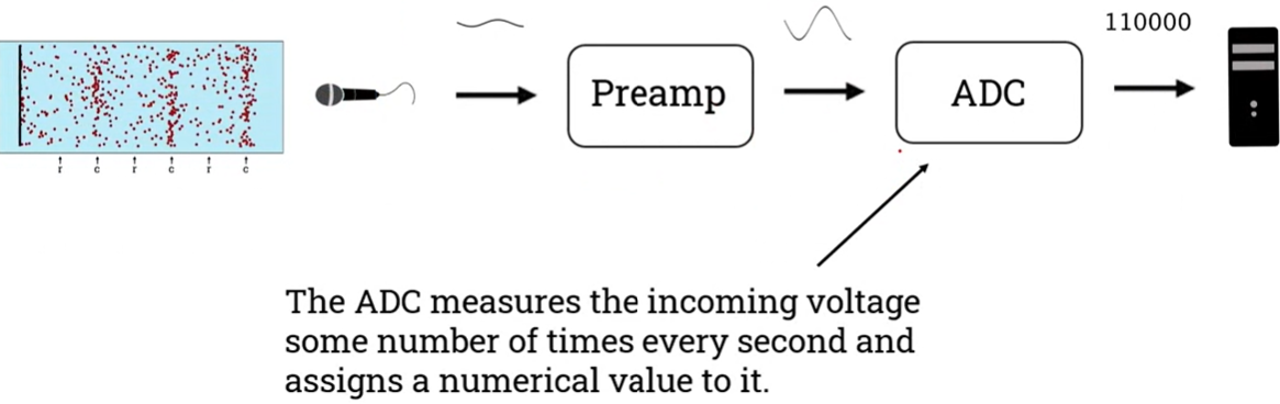
- The microphone (transducer) converts air pressure changes into an electrical signal.
- The electrical energy generated by a microphone is usually quite small, so we need a device, called a preamplifier, to convert the weak electrical signal generated by the microphone into an output signal strong (larger) enough to be digitised.
- ADC samples incoming analogue voltage at a specific rate and assigns a digital value to each sample. These digital values are then usable by the digital devices.
The act of assigning an amplitude value to the sample is called quantising and the number of amplitude values available to the ADC is called the sample resolution.
Once the audio has entered the digital domain, the possibilities for editing, processing, and mixing are nearly endless. When digital audio is played back, the signal is first sent through a DAC.
Digital to Analogue Converter (DAC)
In the opposite case,
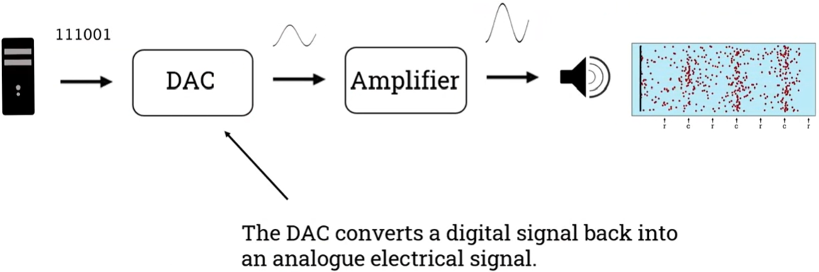
- DAC converts the digital signal back into an analogue electrical signal.
- An amplifier amplifies the level of the signal and sends this signal to a speaker or headphones that will generate the sound wave.
We can perceive the sound wave as a sound. In the context of digital audio playback, the DAC is built into the audio output of the computer or into an audio interface. Some computer speakers connect directly to the computer via USB and therefore have DACs built into them.
Audio recording path summary
- Vibrations in the air are converted to an analogue electrical signal by a microphone.
- The microphone signal is increased by a preamplifier.
- The preamplifier signal is converted to a digital signal by an ADC.
- The digital signal is stored, edited, processed, mixed, and mastered in software.
- The digital signal is played back and converted to an analogue electrical signal by a DAC.
- The analogue electrical signal is made larger by an amplifier.
- The output of the amplifier is converted into vibrations in the air by a loudspeaker.
Sampling rate (frequency)
- Each measurement of the waveform's amplitude is called a sample.
- The number of measurements (samples) taken per second is called the sampling rate (Hz).
The faster we sample the better the quality, but the more samples we take the more memory size we need.
The Nyquist-Shannon sampling theorem
The Nyquist theorem defines the minimum sample rate for the highest frequency that we want to measure. The Nyquist frequency, also called the Nyquist limit, is the sample rate divided by two.

- This theorem says that the signal above the Nyquist frequency is not recorded properly by ADCs, introducing artificial frequencies in a process called aliasing. If the Nyquist theorem is not obeyed, higher frequency information is recorded in too low a sample rate, resulting in aliasing artefacts.
- The sampling rate must be at least twice the frequency of the signal being sampled.
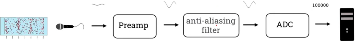
An anti-aliasing filter is a low-pass filter that eliminates frequencies above the Nyquist frequency before audio reaches the ADC.
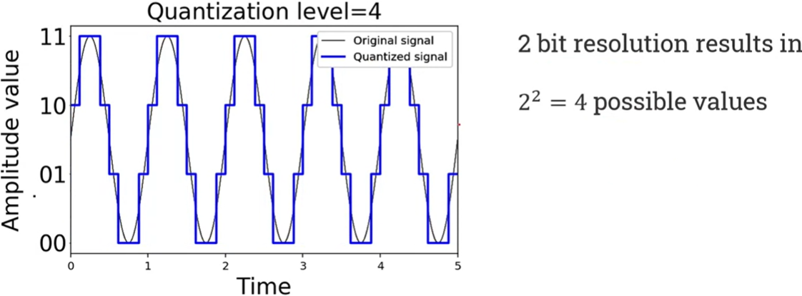
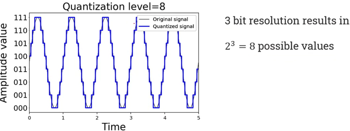
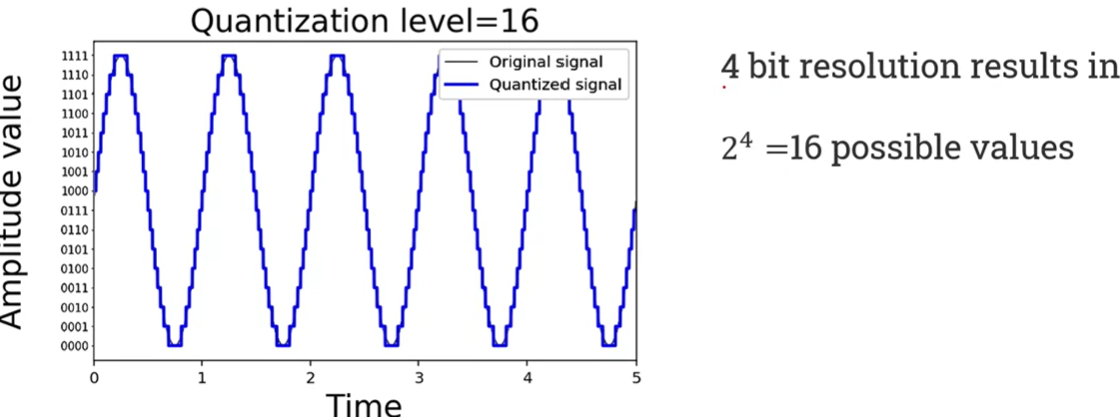
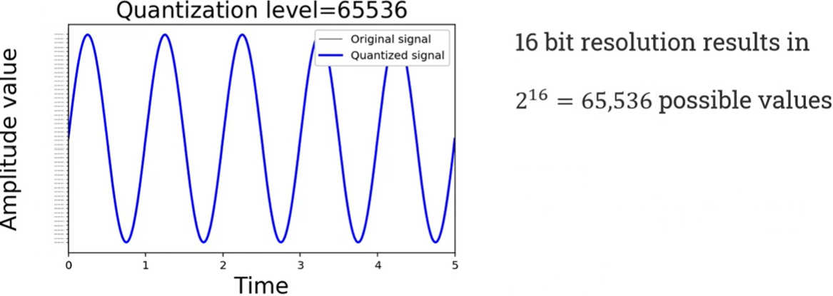
Bit depth
- Bit depth, also known as sample width and quantisation level, is the number of bits used to record the amplitude measurements.
- The more bits we use, the more accurately we can measure the analogue waveform and the more hard disk space or memory size we need.
Common bit widths used for digital sound representation are 8, 16, 24, and 32 bits.

For example, what is approximately the size of an uncompressed stereo audio file, the sound time of which is one minute at a sampling frequency of 44.1 kHz and a resolution of 16 bits? The answer is as follows:
44,100 samples/second * 16 bits * 60 seconds * 2 channels = 84,672,000 bits = 10.584 MB
Clipping
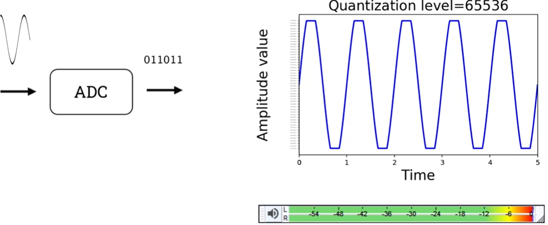
Clipping occurs in an ADC when the analog input signal exceeds the converter's maximum capacity. This overload forces the ADC to assign either the maximum or minimum digital value to affected samples, resulting in a flat-topped or flat-bottomed waveform. This distortion is undesirable and should be avoided. If the level meter reads zero (or the clipping indicator turns red), this means the signal is clipping!
Digital audio representation

All these processes generate an array of samples that we can use to create a new file to process the audio in real-time in the computer, to store the data in a CD, etc. There are two ways of representing digital audio:
1. The time domain representation gives the amplitude of the signal at the instance of time during which it was sampled.
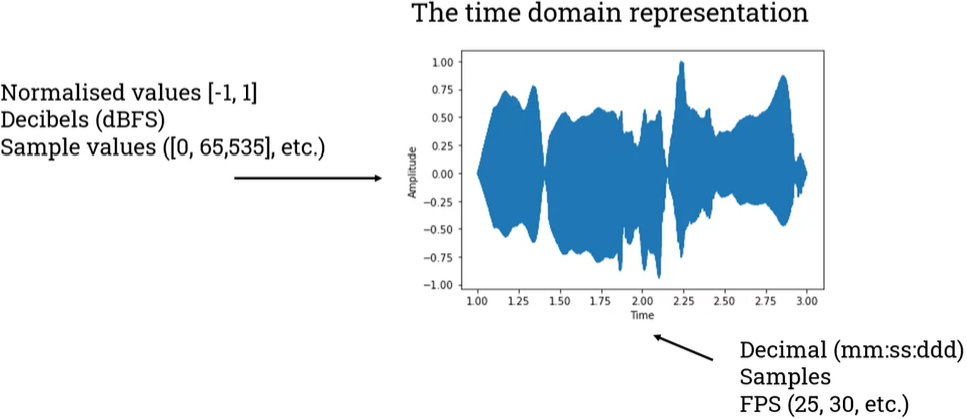
- Time can be expressed as a decimal format. It can also be expressed in terms of samples, for example, we have seconds in the graph.
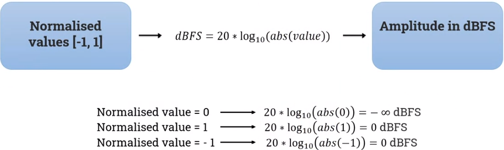
- Amplitude has normalised values between 1 and -1. In using the normalised values, we can find programs that in decibels or even in the sample values.
We can use decibels to represent the values of the samples, but that is not the same as dB SPL. dB FS stands for decibels Full Scale.
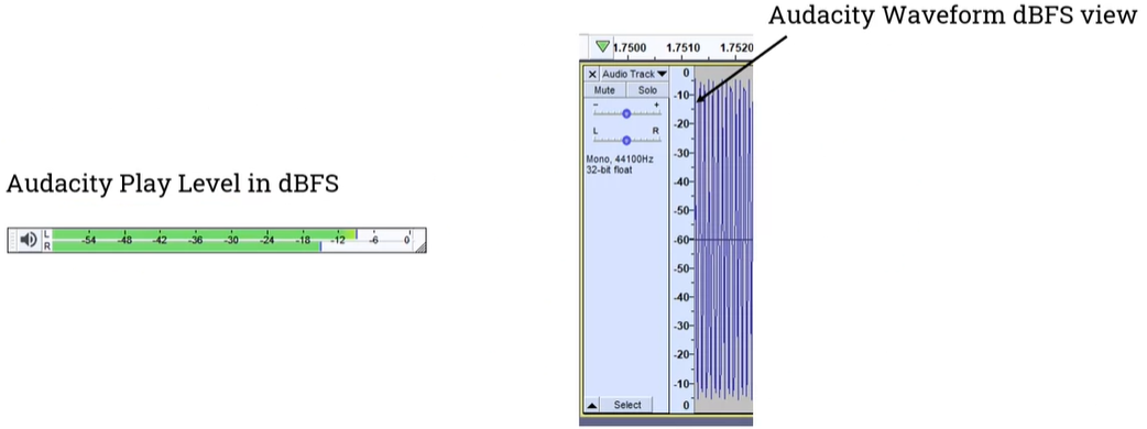
- For example, in Audacity, the meters are in decibels that go from zero to minus infinite.
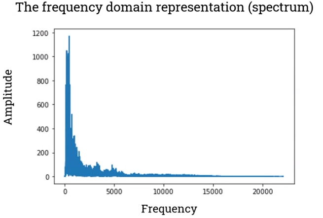
2. The frequency domain gives us information about the frequencies of a sound (sounds can be composed of millions of frequencies as they don't just have one frequency).
A spectrogram is a visual representation of the spectrum of frequencies of a signal as it varies with time.

A spectrogram is very similar to the frequency domain representation, but it provides more information about the time-varying nature of vibration, while frequency domain analyses provide information at a specific moment or as an average over time.
'IntelligentSignalProcessing' 카테고리의 다른 글
| (w10) Offline ASR (Automatic Speech Recognition) system (0) | 2024.06.11 |
|---|---|
| (w06) Complex synthesis (0) | 2024.05.14 |
| (w04) Filtering (0) | 2024.05.01 |
| (w03) Audio processing (0) | 2024.04.26 |
| (w01) Audio fundamentals (0) | 2024.04.11 |